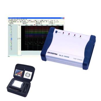
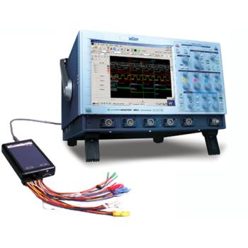
GoLogic™ Logic Analyzer on LeCroy X-Stream based Digital Oscilloscopes GoLogic™ offers all the channels, speed, memory depth, and features of a desktop logic analyzer for a very attractive price. Together with the performance of a LeCroy X-Stream oscilloscope this offers a powerful integrated Logic Analyzer solution. Hardware and software problems are located quickly using GoLogic's™ powerful features and intuitive Windows® oscilloscope interface. ● 36 and 72 channel models ● 2M and 1M samples per channel ● 500 MHz timing analysis on 36 channels ● 250 MHz timing analysis on 72 channels ● 125 MHz state & transitional analysis on all channels ● Pattern, edge and range triggering ● Compact: 3.75" x 6.3" x 1.3" (9.5 cm x 16 cm x 3 cm) ● Run over the Internet or any LAN usig TCP/IP Memory depth (GoLogic U72-1M) Memory depth (GoLogic U72-2M) ● 1,048,576 samples on 72 channels ● 2,097,052 samples on 72 channels Memory depth (GoLogic U36-1M) ● 1,048,576 samples on 36 channels Each model includes one GoLogic™ logic analyzer unit, one 36-channel wire lead set (two for 72 channels), one 12 volt power supply, one 6 ft. printer port cable, one ScopeLink™ cable, one custom carrying case, an illustrated manual, and Windows® 98/ME/NT/2000 logic analyzer software. LEADING FEATURES ● Integrated Logic Analyzer and Digital Oscilloscope solution ● Easy control of Logic Analyzer functions directly from Scope touchscreen or mouse ● Up to 8 oscilloscope traces and 32 logic channels displayed on one screen ● Time alignment within 1 ns between analog and logic timing waveform data ● Long memory supported up to 48 Milion samples of analog data and 2 Million of logic data ● Powerful zoom functions ● GoLogic Analyzer can be you used independently from scope with any external Windows based PC GoLogicTM Additional Features: Timing analysis ● All channels are available at frequencies from 500 Hz to 250 MHz ● 36 channels are available at 500 MHz (2 nanosecond resolution) State analysis ● External clock sources up to 125 MHz are supported ● All channels except one are available ● Up to four channels may be used as clock inputs´ ● Data can be stored on the clock inputs’ rising edge, falling edge, high state, or low state ● A 32-bit time stamp can be stored so each sample’s elapsed time is measured. This is useful when selective storage is used. When not using selective storage, the time stamp can be disabled so the full memory depth is available. Transitional sampling ● Stores a sample only when a transition is detected on a channel. ● Each channel may be defined to detect or ignore transitions. ● Supported on 72 channels at 125 MHz and below ● 32-bit time stamp indicates each sample’s elapsed time ● The memory depth is halved when transitional sampling is used Trigger patterns ● 8 nanosecond trigger resolution ● 8 normal trigger patterns ● 2 edge patterns available in timing analysis mode. Trigger when rising and falling edges are detected on any channel. ● 2 range patterns available in state analysis mode. Trigger when the channel values fall between an upper and lower boundary. ● Range patterns supported on pods A and B (32 channels total). Trigger sequencing ● 8 sequence levels ● 2 normal trigger patterns plus 1 edge/range pattern is detected simultaneously on each sequence level. ● 1 20-bit timer/counter per sequence level while in timing analysis mode ● 1 20-bit counter per sequence level while in state analysis mode ● 1 32-bit global timer ● Sequence actions available when a trigger pattern is detected: Trigger (start capturing data), go to level n, start global timer, increment level’s counter, reset level’s counter ● State analysis mode storage options before the trigger is detected: Store all data before the trigger sample, store no data before the trigger sample, store only data that matches the selected patterns ● State analysis mode storage options after the trigger is detected: Store all data after the trigger sample, store only data that matches the selected patterns Threshold levels ● 2 independent threshold levels (1 per 36-channel lead set) ● Variable between -7.35 volts through +12.45 volts in 40 millivolt increments Probe inputs ● 240 KW input shunted by 15 picofarads ● Maximum 2 nanosecond skew between channels ● 2 nanosecond setup time / 0 hold time Lead set ● Each wire is shielded by a twisted ground wire to reject noise ● High quality terminators fit precisely on round or square 25 mil (0.025 in) pins. ● Color coded and labeled ● Plastic separator-blocks arrange the wires into 8-channel groups. ● Separators slide on wires and can be removed if desired | 


.jpg)
.jpg)


 배송지역 : 전국