|
Product Information
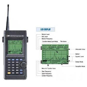
The Aceco FC2002 hand-held frequency counter is
a professional counter with advanced features such as field strength measurement
and auto hold. It is a compact, truly pocket sized, test instrument designed for
ease of use and dependable performance. Supplied internal Ni-Cd pack, AC wall
charger and 7 sections telescopic antenna
Features:
- 10 digit Liquid Crystal Display
- Hi-Z low range
- Filter to prevent display of random noise
- Automatic hold
- Measures frequency and period
- LED back light
- Beeper
- Low power consumption (Average 6 hour battery life)
- Hold switch to lock display
- Low battery indicator
- Ultra sensitive synchronous detector with 16 sections bargraph to show RF
signal strength
- High speed 300 MHz direct counter with 0.1 Hz resolution
- 4 selectable gate speeds
Specifications:
- Frequency range: 10 MHz - 3 GHz
- Weight: 210 g
- Size (H x W x D): 80 mm x 68 mm x 31 mm deep
- Impedance: 1 dual purpose BNC Socket / 50 Ohms input for range 1 MHz to 3
GHz / 1 Meg Ohm input for range 10 Hz to 50 MHz
- Case: Stamped aluminum with black anodized finish
- Battery: Internal 4 x AA 600 mAh Ni-Cd pack
- Power: 9 VDC 300 mA
- Timebase: Less than 1 PPM at room temperature
Input
Sensitivity (Typical)
|
Amplifier |
1 Meg Ohm |
50 Ohm |
|
Impedance |
1 Meg Ohm 30 pF |
50 Ohm VSWR less than 2:1 |
|
Range |
10 Hz - 50 MHz |
1 MHz - 3 GHz |
|
Sensitivity |
< 10 mV at 10 Hz - 10 MHz
< 20 mV at 10 MHz - 50
MHz |
< 0.8 mV at 100 MHz
< 6 mV at 300 MHz
< 7 mV at 1.0
GHz
< 100 mV at 2.4 GHz |
| Max. Input |
100 Vrms |
15 dBm |
RF
Signal Strength Bargraph
|
Frequency |
1st Segment |
Full Scale |
|
27 MHz |
7 mV |
100 mV |
|
150 MHz |
5 mV |
90 mV |
|
800 MHz |
10 mV |
200 mV |
Frequency Display Resolution
|
Range |
Gate Time (Seconds) |
LSD |
Sample Display |
|
300 MHz |
0.0625 |
10 Hz |
300.00000 MHz |
|
0.25 |
1 Hz |
300.000000 MHz |
|
1.0 |
1 Hz |
300.000000 MHz |
|
4.0 |
0.1 Hz |
300.0000000 MHz |
|
3 GHz |
0.0625 |
1000 Hz |
3000.000 MHz |
|
0.25 |
100 Hz |
3000.0000 MHz |
|
1.0 |
10 Hz |
3000.00000 MHz |
|
4.0 |
10 Hz |
3000.00000 MHz |
Controls:
Power Switch - This slide switch turns the
counter on and initiates a 2 second test of all the LCD segments.
Amp Switch - This slide switch selects either
the 1 Meg Ohm high impedance amplifier or 50 Ohm amplifier and
prescale.
Range Switch - This
should be switched to the 300 MHz position for frequencies between 1 MHz and 300
MHz and switched to the 3 GHz position for frequencies between 10 MHz and 3
GHz.
Lite Switch - This slide
switch turns the LCD back light on and off.
Function Button - This selects the frequency or
period. This button has four settings. One each for displaying frequency or
period as these are received, and two settings for automatic hold of the first
frequency or period captured.
Hold
Button - This holds the current display and stops the counter from
counting.
Gate Button - This
selects the gate or measurement time. A longer gate time allows counting for
longer period and results in higher accuracy.
Calibration - The calibration adjustment
opening is located on the front panel of the counter. This allows access to the
trimmer capacitor that provides about a 10 PPM adjustment range of the time base
oscillator. This is not usually necessary but to do so read a signal of an known
frequency before adjusting the trimmer for correct frequency display. If you
calibrate at 4.1943 MHz or above then the counter will be more
accurate.
Reception Distance From
Transmitter
The distance from which you will be able to receive
frequencies will depend upon the type and location of the transmitting antenna,
transmitter output power and the frequency in use. Some typical distances are:
- Cordless Phone - 0.3 meters
- Cellular Phone - 3-20 m
- CB radio - 2-8 m
- VHF Two Way Radio - 3-30 m
- UHF Two Way Radio - 3-30 m
|


.jpg)
.jpg)
.jpg)


 배송지역 : 전국